Exercises
The activity calculates the Rt of different combinations of resistors- assembling these circuits, measuring them, and calculating/explaining any difference founded between calculated (what is expected) and measured (the real one).
How is an experiment carried out to measure resistances in the VISIR?
(See Instruction)
- Enter the VISIR and activate the work area.
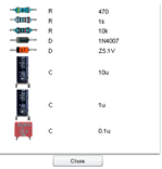
- Now you can see the work area - Breadboard - and you need to click on the sign "+" and then click twice on each of the 1K and 10K resistors (this will give you 2 resistors of each type).
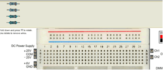
- Now it's time to assemble the circuit. NOTE: all the holes in one column are connected to each other from below (not the rows). Click on a resistor, drag it to the place you want, and repeat the process until you have created the circuit. On the left you will see a series connection, and on the right, one in parallel. The circuit has now been assembled.

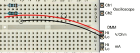
- Once the circuit has been assembled, it needs to be measured. We will use a digital multimeter (DMM) to measure the total resistor value of each assembled circuit. To do this we need to place a wire at one end of the circuit and another at the other end (generally speaking, red and black), being aware that there are many ways to connect wires -all of them valid. On the left you can see how the total resistance of a series circuit is measured, and on the right how this is done for a parallel circuit.
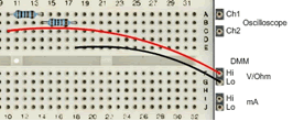
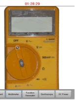
- Finally, we need to activate the DMM for measurement: click on Multimeter (1), turn the dial to the Ohm sign (2) and click on Perform Experiment to measure (3). In this case, a 10 K resistance in series with another 1K resistance behaves like one of 10.99K - in other words, nearly the 11K expected.


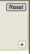
- Return to the Breadboard by click on the "Breadboard" button and assemble and measure a new circuit. When you press "Reset" button, the resistors return to the upper part of the Breadboard interface. The work area is ready for a new experiment.
The following table describes a series of experiments to be performed. The first eleven ones have been assembled, measured and compared, obtaining an absolute and percentage error. The remaining exercises need to be done by the students. Is what has been obtained consistent with what was expected? What is the error of a standard resistor? Do errors accumulate or do they cancel each other out? Which experiment is the most accurate: the simplest (few resistors) or the most complex?
This
experiment can be performed using Google Docs/Excel and/or Excel spreadsheet. [PDF].
