How it works?
The
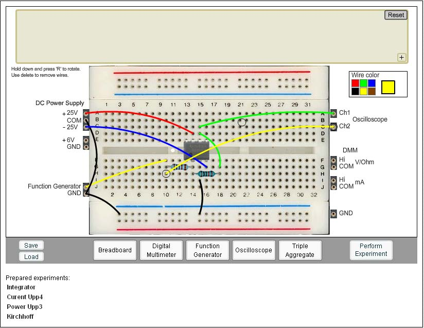
original VISIR online workbench offers the following flash client modules:
• A Breadboard for wiring circuits;
• Function generator, HP 33120A;
• Oscilloscope, Agilent 54622A;
• Triple Output DC Power Supply, E3631A;
• Digital Multi-meter, Fluke 23.
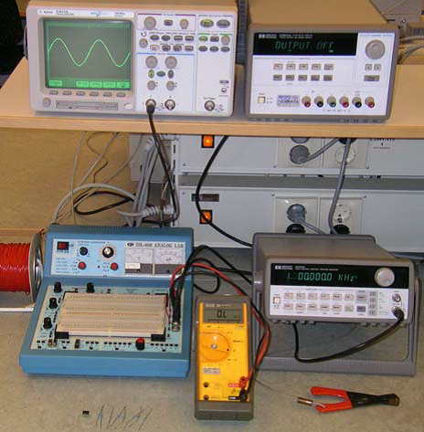
Figure 1 shows a workbench in a
traditional electronics laboratory. Most instruments in
such a laboratory have a remote control option but the solder less breadboard
has not.
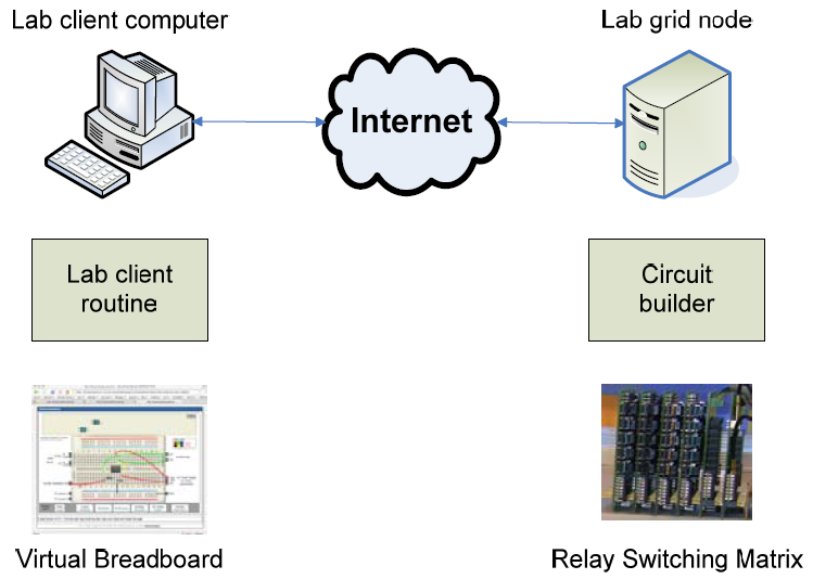
To open a workbench for remote access a circuit wiring
manipulator possible to control remotely is required. A relay switching matrix
can serve as such a device where the relays are arranged in a three dimensional
pattern together with instrument connectors and component sockets.
The small components in the lower left corner of Figure 1 are the component set delivered by the instructor. They are installed in the component sockets of the matrix. Virtual front panels depicting the front panels of the desktop instruments and a virtual breadboard displayed on the computer screen can give distant students the impression that they are working in the real laboratory. A workbench opened in this way can be, for example, a node in a grid laboratory where the virtual breadboard and relay switching matrix combination is a wiring service, Figure 2. The instruments connected to the matrix are omitted.