Experiments with alternating condensers: RC circuits
What happens if a circuit supplied with alternating current a capacitor is included? Well, it is easy to assemble an experiment, measure it and analyse the results.
This type of circuit is known as RC (Resistor-Capacitor) and the simplest one is that comprising one resistor and one capacitor, in our case of 1K and 1uF.
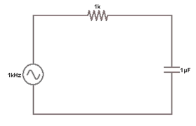
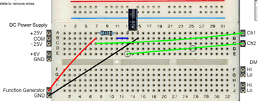
The circuit comprises 1K and 1uF, the input is a sinusoidal f=1KHz (w=2·π·f T=1/f) and Vpp=10 V. The output can be seen on the oscilloscope (the time scales and amplitude are carefully adjusted).
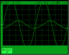
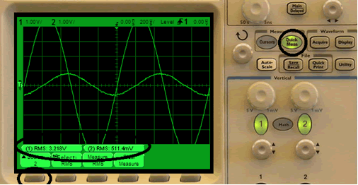
Two things can be seen in the image: that the amplitude has fallen from 5 V to at least 1 V and that the output has been displaced with regard to the input, and there has been a time delay. We can summarize the above in a table [PDF]:
|
Input |
RC values |
Output values |
Interpretation of results |
|
Vi(t) = 5·sin(2·π·1000) Vi eficaz = 3,21 V, T=0,001 s |
R=1 KΩ y C=1 µF |
Vc eficaz = 0,511 V retardo = 219,9 µs |
|
|
Vi(t) = 5·sin(2·π·1000) Vi eficaz = 3,21 V, T=0,001 s |
R=1 KΩ y C=0,1 µF |
Vc eficaz = 2,910 V retardo = 99,99 µs |
|
|
Vi(t) = 5·sin(2·π·10000) Vi eficaz = 3,21 V, T=0,0001 s |
R=1 KΩ y C=0,1 µF |
Vc eficaz = 0,551 V retardo = 22,00 µs |
|
|
Vi(t) = 5·sin(2·π·10000) Vi eficaz = 3,21 V, T=0,001 s |
R=1 KΩ y C=1 µF |
|
|
|
Vi(t) = 5·sin(2·π·10000) Vi eficaz = 3,21 V, T=0,001s |
R=1 KΩ y C=10 µF |
|
|
|
Vi(t) = 5·sin(2·π·10000) Vi eficaz = 3,21 V, T=0,001s |
R=1 KΩ y C=10 µF |
|
|
How is the delay in the output measured with regard to the input? Firstly, we need to activate the Cursors option, then X1, then turn the upper dial until the vertical line reaches the point desired (where the input cuts across the horizontal axis), then select X2, then turn the upper dial until the vertical line reaches the point desired (where the output cuts across the horizontal axis), and lastly, DX can be read in the lower left corner, which in this case is 219.9 µs. In other words, the cut across the horizontal axis has been marked as a reference point, one cursor has been moved for the input, and the same has been done for the other cursor with the output. The oscilloscope provides us the results.
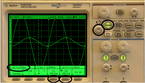
The effective values are obtained just as before. Now two signals should be measured. For this we need to know how to change from Source 1 (the input) to Source 2 (the output).
